|
|
|
" Kennedy Yacht Design "
" Welcome to Ken's multihull Heaven "
Talk multihull's with Ken
|
Let’s talk about boat design and amateur boat construction from the perspective of an architect whose yacht
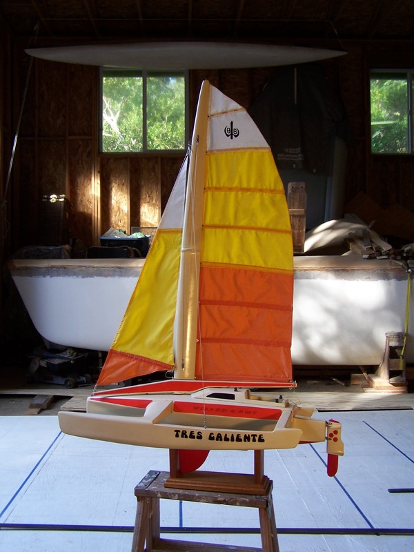
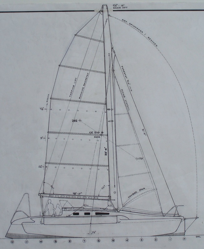
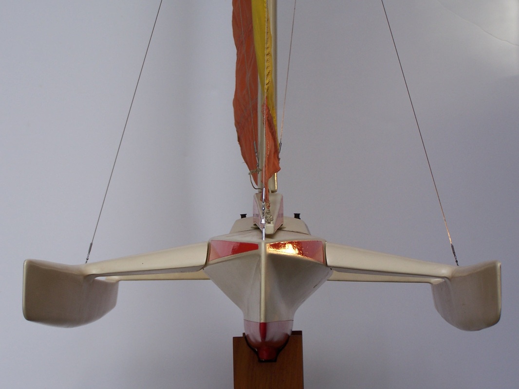
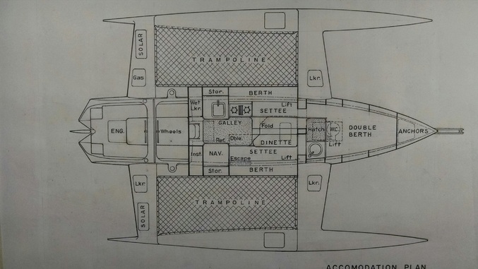
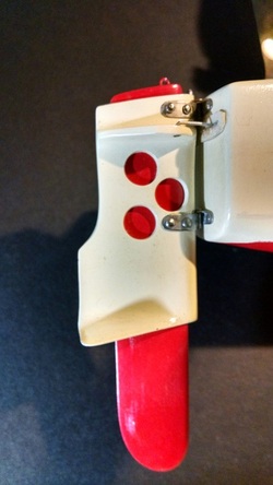
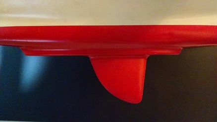
design practice has been an avocation rather than a vocation. My business is primarily land-based structures. But these lack the organic nature of sailing craft, which interact dynamically with their environment….one which is always changing. This is close to creating a living organism. No wonder we always imbue our boats with names and personalities. I had a part in Rob Sallette’s Big Easy when has asked me to design an accommodation, deck, and sail plan apart from the stock setup. So she is a staysail schooner with a wheelhouse, bowsprit, flush deck, and set up to be charter-capable. I still think the resulting profile (side view or elevation) is strikingly beautiful. I’m anxious to see her under full sail. At the same boatyard as Rob I built a 37’ trimaran, modified from a stock plan. This was home and adventure vehicle for my family for ten years. Sailing this boat (engine less for three years) did two things: converted me to multihulls, and finalized many of my ideas about proper hull shape, construction, and rigging. My current project is the design-build of a 32’ trimaran, the Wizard 9.6MT. I hope to have a continuing presence on this website to discuss various design aspects as they relate to this particular boat. I’ll start with the initial planning and concept. Here was my requirement list: >Size to be trailer-able, or rather transportable by road-legal width >Full headroom, berths for four or five. >Unswampable, with self-righting capability in event of capsize. >Simplified, lower cost construction. Fewer exotic and expensive materials. >Not a racer but a cruiser, easily driven with a modest wing-mast sail plan. In regard to this last requirement, the key is reduction in both skin and form drag of the immersed (canoe body) hulls. Of the many-drag design parameters to look at, two functions are most important; the waterline Length:Beam ratio, and the prismatic coefficient. For the former, mono hulls, which are burdened with ballast, can’t practically be designed with an LBR much greater than 7:1. Their form puts them fully in the displacement wave-making mode, and no matter how much power is applied they cannot escape their own hole. (we’ll talk about surfing later, for planing is the only possible escape.) To have a hull which can escape this limit (usually expressed as a function of the square root of the waterline length), the LBR needs to be approaching 10:1 or greater. Once past the displacement hump, the form drag greatly diminishes, resistance drops, and much greater speeds are possible with a given sail area. Research has shown this benefit to be greatest around 14:1, with reduction thereafter. Such slender hull shapes are best possible in multihulls. For the W9.6MT, acomodation and weight-carrying demands led to a final main hull (or vaka) figure of 12:1. Float hulls (or amas) could be 14:1. While seeming less-critical from a volume standpoint, the amas still need to have a fully-immersed displacement of at least 1.4 of the total boat weight. (there are other schools of thought on this: some successful trimarans have had low-volume submerged amas, but these lack the capsize safety factor of a practical cruising boat.) Imagine taking the cross-section of the immersed hull at its greatest girth. This needs to be somewhere aft of the mid-point considering pitching, weight, and shape requirements. Now create a solid, or prism, by extending this the full waterline length. The ratio between the actual designed displacement and this “prism” is the prismatic coefficient. One can immediately see how this ratio is affected by many aspects of the canoe hull: forefoot;, rocker, and stern bustle as seen in profile, bow angle and fullness in the ends of the waterlines. Heavier displacement monohulls are likely to be in the low to mid .5’s, some multihulls may fall in the upper .5’s. There is no ideal prismatic coefficient for all boat speeds or displacements: higher Cp’s up to around .8 favor higher but diminishing design speeds. For any design speed there is a prismatic which results in the least drag. For a multihull, we can use higher design speeds, and thus higher Cp’s are favored. The W9.5MT has .662 , for a design ;hull speed of 12 knots at least relative drag.. An advantage of the rather full-ends required by this figure is greater volume and displacement. Another form of drag is one we’re all familiar with: skin, or wetted surface drag. Chine hulls are likely to be slower because they have more surface area. Clearly, the hull shape giving you the least wetted surface for a given displacement is a true semi-circle. Successful boats have used this shape. However this limits hull volume. By hardening the bilges with more of a hyperbolic shape, greater volume is possible with proportionately very little extra wetted surface. Such a hull shape at greatest girth is very easily transitioned aft to fuller and flatter lines there, helping with pitch-dampening and promoting surfing. The design of the W9.6MT was improved by the construction of a radio-controlled model. While calculations can do this too, the real-world testing (after applying exponential scale reduction) told me that full-sail capsize would occur at 25 mph windspeed. This might be acceptable for a racer, but it was not for my cruising design. Appropriate changes to hull forms, design displacement, and rig were made when the lines were finalized. A last note here: The model is of a lighter sport-cabin version with a stayed aero-rig. Plans for the W9.6MT, while having the same hulls, show a larger cabin and rotating wing rig. " THE TEST MODEL"
|
For Consultation on design Quote's Contact in the Box Below
|
|
" ©2015 kennedy yacht design“All Rights Reserved”
Contact : [email protected]
|
INSTALLMENT 2
PARTICULARS
LOA 32’-9.75” (10.0 m)
LWL 31’-3” (9.53m)
LENGTH Amas 29’-0” (7.93m)
BEAM OA 22’-0” (6.70m)
BEAM Vaka 8’-5” (2.57m)
BEAM WL 2’-7.25” (.794m)
DRAFT Canoe hull 1’-5.5” (.445m)
DRAFT Board up 1’-9” (.533m)
DRAFT Board dn 5’-6.25” (1.68m)
DISPLACEMENT Racing 3569 Lbs. (1618kg)
DISPLACEMENT Cruising 4779 Lbs. (2167kg)
AMA BOUYANCY Submerged Flooded 1149 Lbs. (521kg)
DLR Racing 53
DLR Cruising 71
FINENESS Ratio Vaka 12:1
FINENESS Ratio Amas 14.5:1
PRISMATIC Vaka .662
PRISMATIC Amas .640
SAIL AREA Main 294 sf
SAIL AREA 100% FT 176 sf
SAIL AREA Wingmast 48 sf
SAIL AREA Total 518 sf (48 m2)
THE FOREFOOT
As seen in profile
As we look at the appearance of the forefoot, i.e. the profile of the keel seen as it
approaches the waterline at the bow, and particularly as it relates to multihull craft, a
design trend has been seen: The forefoot has been cut away to the point where the keel
line follows almost a straight line to the waterline exit forward, thence intersecting an
almost plumb bow at an angle only slightly relieved by minimal curvature.
This is a design luxury not afforded to conventional displacement sailboats, where
the required hull volume must be carried to the bow, both for weight support and to resist
sail forces forward. Later monohull designers did start some departure from the old “full
ended” concept when they cut away the full-keel profile in transition to a more fin keel
profile. This gave more maneuverability and less skin resistance where lighter
displacement boats were evolving.
Multihull hull design, particularly the center hull, or vaka, of the trimaran, gains
some apparent advantages by so doing (and remembering that, again, ever lighter total
displacement due to modern materials has allowed it):
1) With less bow immersion, the boat is quicker in stays, i.e. less lateral resistance
to turning. Quicker response to the helm.
2) For planing hulls, the bow will lift sooner, transferring hull plane aft to the now
normal flatter sections. An advantage in racing where a large rig is supplying
plenty of power.
3) No tendency to dig in when power reaching or running and in large following
seas.
4) No harm from loss of hull volume pitch control, as the forward sections of
the amas are full enough to dampen pitching. (for cats, it is somewhat
different, but here one still sees the forefoots cut away while aft sections are
designed fuller to forestall the pitch)
But yet, when designing the Wizard 9.6MT I did not use a radically undercut
forefoot, rather a more spooned shape. So the keel profile does not rocker up
steeply but rather follows a more gradual level curve before the bow transition.
(There is a design precedent for this: Dick Newick’s 36’ White Wings. I was not
trying to replicate this boat, which is radically different with a freestanding yawl rig
and “new moon.” amas.) I arrived at the design decision by other analysis. So
why did I do it?
1) This is not intended as a racing boat, but a somewhat heavier cruiser, so it was
. cruising attributes I was looking for. The fuller forefoot allows a longer, less
rockered run of keel for superior tracking and a less touchy helm. This in turn
allows for less strain on self-steering apparatus; a less fatiguing helm. It not
being a round-the-buoys racer, I was willing to sacrifice some quickness in
turning, though she will still come about nicely with the large centerboard.
2) Better pitch control, with more volume distributed forward to counter the after
area; less rocker. Larger prismatic coefficient, as previously mentioned.
3) With heeling, she will preserve the length of waterline through a greater range.
The already better pitch control is kept without diminishing with heel.
4) More lateral resistance with heeling, less board dependent. Also, there is still
more boat in the water as she heels, increasing heeled stability.
5) Here is the main reason. This main hull was designed to be an easily driven
hull, allowing a safer and smaller sail plan. Therefore, the canoe body is
optimized for least hull resistance at lower speed ranges. Two particular
functions were chosen to so optimize (based on fluid analysis by others, i.e.
Marchaj and Norwood): Hull LBR and prismatic coefficient. The LBR, or
length to WL beam ratio, is nearly optimal at 12:1, and maintains this through
a range of heel, not rapidly diminishing as with the planing oriented forefoot.
The prismatic coefficient, at .662 is most ideally efficient over the expected
speed range. It is impossible to have this high a prismatic with the cutaway
forefoot; you simply can’t get it with a diminished volume distribution
forward.
6) More power from the forward sections on a reach.
7) As to the issue of possibly “tripping” around the deeper forefoot when running
before seas: I concede a reduced ability to sideslip a possible broach. But I
counter this with a larger rudder and less fatiguing, more easily handled helm.
Besides, the planing hull is really powering and surfing such seas; the greater
speed makes a broach more likely to begin with, so you need the cutaway
forefoot!
"THE AMAS"
The relation between a trimaran’s amas and vaka (outriggers and main hull) is a
dynamic one much different from the two hulls of a catamaran. This is why some attempts
I’ve seen to convert tri amas to a catamaran have failed. The latter’s hulls are of course
identical, and must share the vessel’s weight at rest and trim out at the same time, at all
heel angles. Only in racers do cats lift a hull, and then sailing is at the knife edge of
capsize. We want a trimaran’s vaka to lift, preferably quickly, which is why they are
designed to just kiss the water at rest.
But at that point, the windward hulls are just along for the ride and their
aerodynamic drag is detrimental. So here a compromise is needed: to have enough
volume for seaworthiness in the leeward mode, but not contribute to total drag. Some
design solutions to reduce the windage have used low-height, wide body amas with flat
planing bottoms. Some pounding must be expected here. There are other dynamic
complexities. As the tri heels, more of the vessel weight is borne by the ama. If its center
of immersed buoyancy is exactly athwart that of the amas, then as the main hull comes out
of the water, so does the rudder. Ergo loss of steering. In some racing tris, particularly
larger ones, which are sailed much like racing cats in that the aka is flown, the only
solution has been twin rudders on the amas.
But we are dealing with a cruising boat here, and the aka is not flown (just as
cruising cats have no business flying a hull.) We can keep the rudder down by having the
ama center of immersed bouyancy move forward with increasing heel. This is done
through changing the rising waterlines to ever more fullness in the forward sections. This
serves another purpose as well: Monohull sailors know that as the boat starts to run off
and the boom is let out, the center of sail effort moves outboard, creating a yawing
moment that wants to round the boat up. Spectacular broaches can occur. But even so a
windward broach is something of a safety valve. In a tri, we don’t want to broach at all
when over-pressed on a power reach, which can lead to capsizing over the lee hull. As the
tri heels onto its ama, the overall center of buoyancy of the vessel moves forward and
outboard. The sail center of effort moves this way too, but is counteracted by the ama.
The result is lee helm with increasing heel, The boat keeps upright and can handle the sail
forces.
As the tri surfs down a wave face, it can easily reach speeds which overtake the
wave ahead. Hulls are driven under, and can capsize over the submerged lee hull. I’ve
been in this near situation a couple of times on my old boat. Too much sail up, yes, but it
lacked fullness forward in the amas.
To look at how the ama design of the 9.5MT addresses all these factors: The hull
bottoms have a slight vee to avoid slamming and a modest bow rake for wave piercing.
The foredecks are completely rounded all the way back to the front crossbeam (vaka.) for
reduced windage and wave penetration. The hull bottoms are not radically rockered aft,
to keep some reserve buoyancy there in the event of the boat stalling and being pressed
back on her lee quarter. I calculated resting configuration at both a “racing” weight
(basically bare boat with crew of 2) and a fully-loaded “cruising” weight. In the racing
mode, the ama bottoms kiss that design waterline. In cruising mode, they are immersed 3”
I like this compromise; the boat rocks less downwind and when boarded at dock or
anchor; there is more stability at anchor for a quiet night’s sleep; and when sailing this 3”
is quickly dissipated with heel.
Ama slenderness, or WL LBR is 14:1, as mentioned for least form drag, and they
carry this ratio exactly throughout the heel range! Many tri amas (if not most) are drawn
in profile with forward raking transoms. I don’t dispute that these look really racy, but
what happens when they immerse? For one, the waterline decreases rapidly and smooth
exit flow is impossible. Look at pictures of fast heeled tris and see the rooster tails
coming off these turbulent transoms. The 9.5MT, with her modest sail plan, doesn’t
need any superfluous drag I call these aft raked transoms canoe sterns. While not the
same in profile as a traditional canoe stern, they do have a fine trailing edge at all heel
angles. Are they ugly? Well, function over form.
"THE KEEL"
KEEL
Determining the means of lateral resistance requires an analysis that considers the
intended use of the boat. In this case, a “real world” cruiser. One of the features I insisted
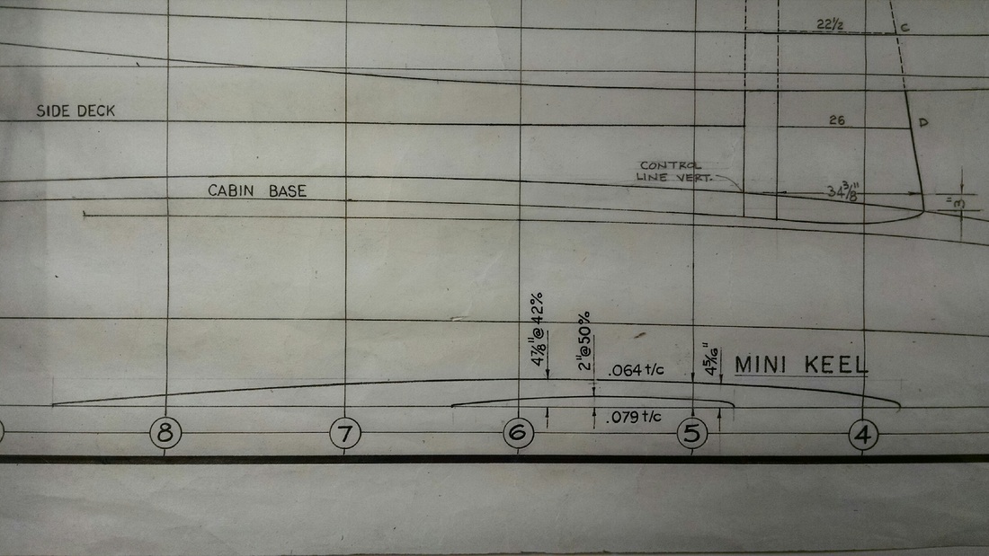
on was the low-aspect foil keelson, or “mini-keel”. Consider this a sacrificial shoe, its
purpose is to protect the main hull in case of grounding. It has the added benefit, as I
found on my previous trimaran, of allowing full access to the bottom of the hull when
beached for bottom work or maintainance, and a good place for blocking up in a yard , as
its beam strength precludes putting too much concentrated stress load on the hull.
Another benefit, as we’ll find, is to allow a lower pivot axis for the centerboard, thus
increasing board draft.
We accept a penalty in increased drag and wetted surface, but does the mini-keel
give any sailing benefit? There is the obvious one of increasing directional stability. If it is
designed longitudinally with lifting foil sections, then it can suffice for tacking in shoal
waters with the board up, or for downwind sailing in the same configuration. For this
latter we do not need high-lift (and therefore high drag) sections. This is a good point to
discuss foil shapes and how their parameters affect what we want the foils to
accomplish.
Unlike wing foils for aircraft, fixed foils in the water flow of vessels must provide
lift equal and bilaterally, in the direction of the yaw; another way of saying they have to
work on both tacks. Therefore they must be symmetric about the longitudinal axis; lift can
then only be generated by angle of attack….another way of saying you can’t have a
sailboat tack with no leeway. Some measurements of the foil shape help promote lift:
1. Thickness ratio is the maximum foil thickness to chord, or foil length. Higher
values here (up to a point) provide higher lift and are more forgiving in that
they increase the stall angle, or point where the flow disrupts on the low
pressure side. But drag is also increased.
2. Leading edge radius: Larger increases the lift-drag ratio.
3. Position of maximum thickness: Locating this at a point about .3 aft of the
leading edge increases the lift-drag ratio. At points around .5 of the chord
length, drag is reduced at angles of attack near zero. These are called laminar
flow sections because the moving water molecules remain attached in a
drag-reducing way to the skin.
Families of foil shapes, such as the NACA sections, have been worked out by
scientists far smarter than me for intensely specific uses. For this cruising design we can
keep it simple. The mini-keel, because it is so long, already has a small thickness ratio for
reduced form drag. Since it will be there for downwind sailing with the board up, when
we don’t need as much lift and are not worried about stalling, a “laminar flow” section will
reduce turbulence and drag, so the point of maximum thickness is moved aft to the mid
point. Also, the mini-keel gets a tight leading edge radius (think cleaving the water more
cleanly.)
"THE CENTER BOARD"
CENTERBOARD
There’s no question that for least drag, higher speeds, and best pointing ability,
high aspect (deep) daggerboards are best. But you have to deal somehow with the threat
of collision at speed. Racers may take the risk. I once stood on a pre-race dock as the
delivery crew of a maxi racing trimaran carried their destroyed (large) daggerboard off the
boat. They’d hit a submerged log on the way in. There was no spare. The race was over
for them; there was interior damage as well. There are ways to mitigate the threat, but
these do add some complexity to a simple situation. .
Yet when designing the 9.5MT I have opted for a pivoting centerboard. This
decision was solely based on the “real world” mission. There is ever more and more junk
in the oceans; in my previous tri I did hit awash timbers and barely avoided a 55 gallon
drum which would have holed me for sure. (not sunk….another huge advantage of a
trimaran that I will expound upon later.)
We all know the disadvantages of pivoting boards: They have lower aspect ratios
and therefore do not point as well; they have higher resistance, the trunks take up valuable
cabin space, and the turbulence of their open slots make them real “drag queens.” But
having made a commitment based on having a safer means of leeway prevention, how to
mitigate these?
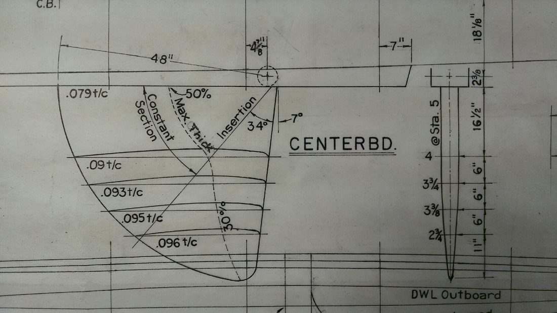
First is to design the board so that it completely fills its slot at varying depths of
deployment, just like a daggerboard. The only way is to have constant radial foil sections
about the pivot. Obviously, when you do this and look at the water flow at various
depths, with the board fully extended, there is a transition in horizontal shapes seen by the
flow. The position of maximum thickness shifts forward with depth, so that the
lowermost “seen” sections are of a high lift type advantageous for going to windward, as
well as being less apt to stall at varying angles of attack as the tip of the board may
oscillate with boat roll. The higher sections transition back to more of the “laminar flow”
type, best for least drag and downwind sailing. With the board in the partly retracted
position, the laminar flow sections predominate, and there is still enough lateral resistance
for deep reaching.
The foil shape is designed with a large leading edge radius for best lift-drag
performance for going upwind. As the board is retracted, this fullness diminishes in the
apparent direction of flow, reducing that feature’s drag penalty. Finally, the tip below the
partly-retracted line is given a pointed shape since this becomes the trailing edge in that
position.
There is no perfect design for all situations, but I am happy with this compromise
centerboard.
As for the trunk, it logically becomes the center of a folding dinette table. The
downhaul pendant, just like for the rudder, has a quick release for emergency
kick-up….remember also that this board floats. One more refinement is that the inside of
the trunk is lined with copper sheet, for a couple of reasons. This is an area hard to
access, so there is no need for antifouling paint here. This now becomes a superior place
to ground for lightning protection and for HF and SSB radio operation.

